Determining Position
If there is only one satellite available to a receiver then the only thing the receiver can do is to determine the distance of the satellite from itself. We cannot calculate the position of the receiver as it could be at point defined by an imaginary sphere with that radius.
How to know the position?
Let's take another satellite, now we have 2 satellites, so now we can tell that the receiver lies somewhere between the intersection of the two spherical ranges.
When we take 3 satellites then we narrow down our range to two points which are the intersection of the three imaginary spherical ranges. GNSS receivers are smart enough to choose the location nearest to the earth's surface.
In a nutshell :-
- 1 range puts user on the spherical cone.
- Intersecting with a 2nd range restricts user to the circular cones
- A 3rd range constraints user to 1 of the 2 points. The satellites choose the one which is closest to the earth.
The more the number of satellite the better the precision.
Position Equations
These non linear equations are solved iteratively using an initial estimate of the user position, XYZ and b -same for all satellites.


Where:
Pi = Measured Pseudorange to the ith SV
Xi, Yi, Zi = Position of the ith SV, cartesian coordinates.
X,Y,Z = User position, cartesian coordinates, to be solved-for b = User clock bias(in distance units), to be solved for
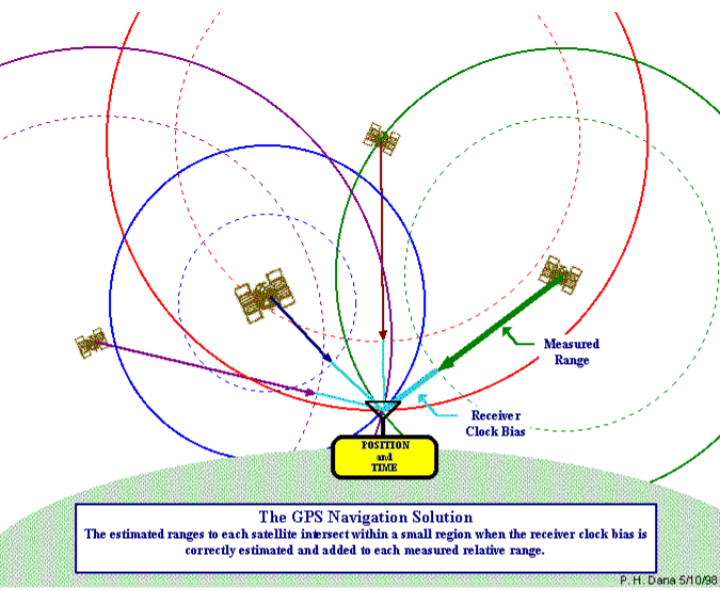
How GNSS Works?
- First a GNSS receiver detects a 1-way ranging (Range = Time taken x Speed of light) signals from several satellites
- Each transmission is time tagged.
- Each tansmission contains the satellite's position.
- The time-of-arrival is compared to time-of-transmission.
- The ΔT is multiplied by speed of light to obtain the range.
- Each range then puts the user on a sphere about the satellites
- Intersecting several of these spheres yields a receiver position.
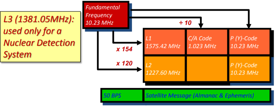
GPS Time and Signal Structure
The GPS satellite clocks are essentially synched to International Atomic Time(TAI)
- TAI is the basis for UTC, used for most civil time keeping.
- GPS time = TAI + 13s
Each GPS Satellite transmits a number of signals. The signal comprises two carrier waves (L1-19 cm and L2-23 cm) and two codes (C/A on L1 and P or Y on both L and L2) as well as a satellite orbit message.
Bandwidth allocated for L1->24 MHz, L2-> 22 MHz, L5 -> 28 MHz
Code Modulation

Selective Availability(SA) : To deny high accuracy real-time positioning to potential enemies, DoD reserves the right to deliberately degrade GPS performance (on C/A code: deactivated on 1 may, 2000)
Accuracy: The degree of conformance of that position. Since accuracy is a statistical measure of performance.
Coarse Acquisition(C/A) Code
It is originally intended as simply an acquisition code for P-code receiver.
It modulates the L1 only. The chipping rate = 1.023 MHz(λ = 290 Meter)
Sequence Length = 1023 bits, thus Period = 1 milli second.
Provides the data for Standard Positioning Service(SPC): The usual position generated for most civilian receivers. It is modulated by the Navigation/Timing Message code.
Coarse Acquisition(C/A) code: A pseudorandom string of bits that is used primarily by commercial GNSS receivers to determing the range to the tansmitting GNSS Satellite. The 1023 chip GPS C/A code repeats every 1ms giving a code chip length of 300m, which is very easy to lock onto.
Precise(P) Code
- It is generally encrypted into the Y-Code(A.S) – Requires special chip to decode
- Modulates both L1 & L2 – Also modulated by Nav/Time data message
- Chipping rate = (λ = 29.30) i.e. 10 times faster than C/A code ensuring improved time measurement.
- Sequence Length = 2.35 *1014 bits, thus period = 266 days
- P-Code rate is the fundamental frequency(provides the basis for all others)
Navigation Message
In order to solve the user position equations, one must know where the SV is,
- The navigation and time code provides this. 50 Hz signal modulated on L1 and L2
The SV’s own position information is transmitted in a 1500-bit data frame
– Pseudo-Keplerian orbital elements
- Determined by control center via ground tracking – Receiver implements orbit-to-position algorithm
- Also includes clock data and satellite status
- And ionospheric / tropospheric corrections
- The International Telecommunication Union (ITU) has reserved 1559-1610MHz band for satellite based navigation through World Radio Communication (WRC) conferences, held every three year.
- GPS bands (US Federal Communication Commission): (1215-1240MHz, 1559-1610 MHz, L5- 1164- 1188MHz)
Structure of Navigation Data
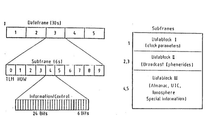
Navigation data records is divided into three data blocks:
- Data Block-I : Appears in the first sub frame & contains the clock coefficient
- Data Block-II : Appears in the second and third sub frames and contains all necessary parameters for the computations of the satellite coordinates.
- Data Block-III : Appears in the fourth and fifth sub frames and contains the almanac data with clock and ephemeris parameter for all available satellite of the GPS System.
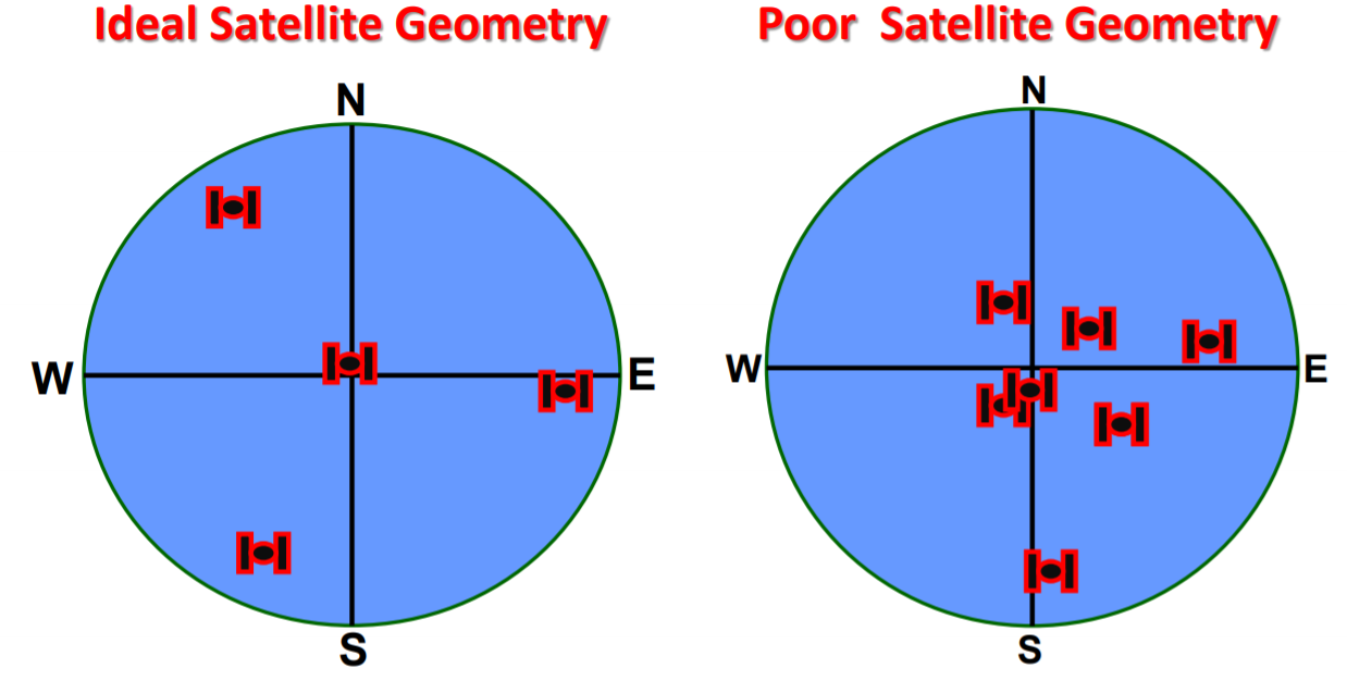
Satellite Geometry
- Satellite geomtry can affect the quality of signals and accuracy of the receiver trilateration
- PDOP reflects each satellite's position relative to the other satellites being accessed by a receiver.
- PDOP can be used as an indicator of the quality of a receiver's triangulated position.
- It's usually up to the GPS receiver to pick satellites which provide the best position trilateration.
Satellite Mask Angle
- Atmospheric refraction is greater for stellites at angles that are low to the receiver because the signals pass through more atmosphere.
- There is a trade off between mask angle and atmospheric refraction
- Setting high mask angles will decrease atmospheric refraction, but it will also decrease the possibility of tracking the necessary four satellites.

Ideal and Poor Satellite Geometry
Services